| This page ends here - we left Ridgefield, CT for Seattle, WA on August 6th and the story picks up on the Re-assembly page - almost one year later on June 6th, 2004. |
|
|
21 June 03 and I've been re-assembling 038 for the past two weeks. I've been having difficulty updating the web page because I am learning how to use Adobe GoLive as I go and that's not a smart thing to do. I should spend a day learning how to use this program and re-create this entire site - but I'd rather install bolts and shoot rivets. Someday, when the rain stops, I'll get to fly the Nimbus - but that may be a long time coming.
|
 |
| Skin shot on and floor pans installed. I 'm working on the nose longeron installation now. |
 |
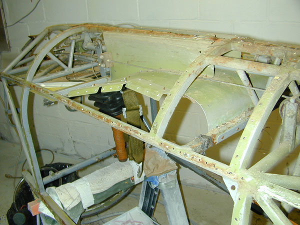
| The canopy frame was completely disassembled, cleaned up and primed with white epoxy. |
 |
|
 |
|
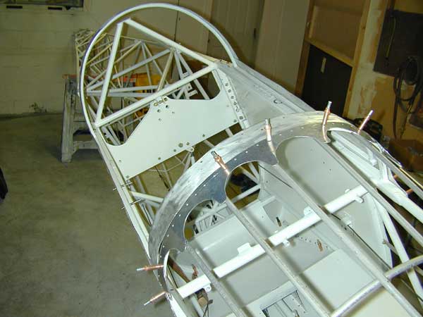
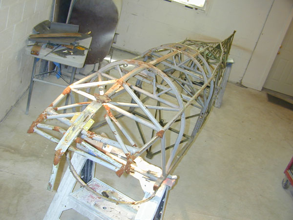
June 29 - above and below - the side ribs are fabricated from aluminum and riveted to the fuselage. The longerons are installed and the glider is almost ready for covering. The flight controls and cables are all installed and safetied.
|
 |
|
 |
| Side ribs getting the stiffeners riveted in place. |
 |
| The old wooden side rib being used as a rough pattern for the new aluminum ribs. .032" thick 2024-T3 |
 |
|
 |
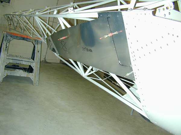
| June 28 Nose bulkhead is fabricated. Above June 29 - Bulkhead is riveted. |
 |
|
 |
|
 |
|
 |
|
 |
|
 |
|
 |
|
 |
|
 |
|
 |
|
 |
|
 |
|
 |
|
 |
|
 |
|
|
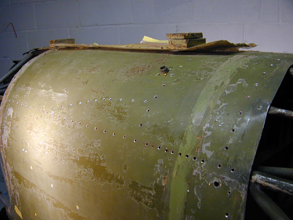
| The CherryMax CR3242-4-3 rivets sit nicely flush in the original countersinks. You can see the regular MS20426AD4-4 rivets that attach the seat pan support structure to the cockpit skin. The dirty marks around the rivets are from the flat set I used to shoot these. |
 |
|
|
|
 |
|
 |
| Details of the clever rivet puller - available from Aircraft Spruce for about $50 and worth every penny. |
 |
|
I'm using the very nice CherryMax rivet puller to pull the rivets. Sure saves a lot of wear and tear on your hands.
|
 |
I ream the holes with a #27 drill to accomodate the oversize shank of the CherryMax CR3242 rivets.
|
 |
|
Cockpit skin clecoed into place.
|
 |
|
 |
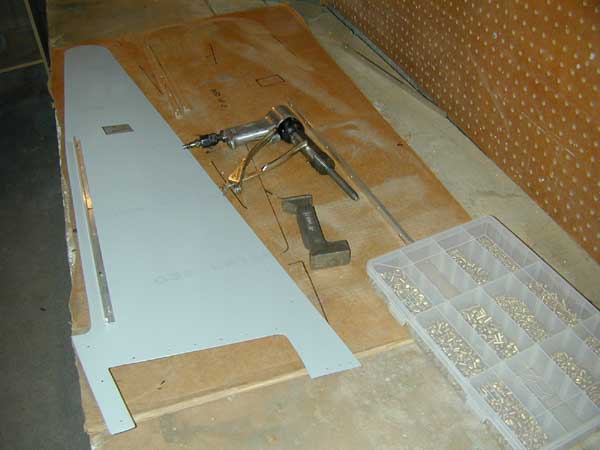
| The cockpit skin has the seat support structure riveted in place prior to installation onto the fuselage frame. |
 |
| I have run the cables, installed the flight controls and spar carry-through structure and tightened and safetied everything that lives down below in the cockpit prior to installing the cockpit skin. this will save a lot of bending over and fiddling around where I can't see what I'm doing. |
 |
|
Details of the parts installations.
|
 |
|
 |
| I have run the cables, installed the flight controls and spar carry-through structure and tightened and safetied everything that lives down below in the cockpit prior to installing the cockpit skin. this will save a lot of bending over and fiddling around where I can't see what I'm doing. |
 |
| That's about half of the new hardware I ordered from Aircraft Spruce for the re-assembly. |
 |
|
 |
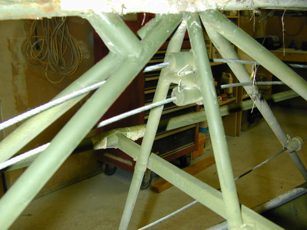
| Prior to installing the control tube and aft spar carry through tube, I clean the inside of the tubes with a wire brush and fill the tubes with paint to prevent future corrosion. In this photo you can also see the good, used release arm sent to me by Jeff Daye - thanks Jeff! |
 |
| 1 June and the fuselage is primed with Polyfiber white epoxy primer. |
 |
|
 |
|
 |
| 14 June - Parts being installed, turtledecks getting painted. |
 |
| May 31, 2003 - The fuselage is finally rust and paint-free. It's taken two weeks of sand-blasting, grinding, wire brushing and filing to get all of the rust and paint and primer off every bit of the fuselage frame, but now it is done. Ready for Polyfiber epoxy primer. |
 |
|
 |
| Looks better now after sandblasting and wire-wheeling - no rust, no kinks, no repairs. |
 |
| I stripped the yellow paint from the aft and forward turtledeck and canopy frame. The new canopy arrived today so I now have everything needed to complete the glider. |
 |
| Removed from the rotisserie to get all of the pieces wire brushed and ready for paint. |
 |
| May 11, I weld the nose fairing support tubes into place and replace the broken instrument panel nutplate tab. This completes the fuselage welding portion of the glider rebuild. |
 |
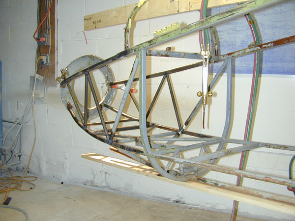
| The support tubes for the forward fairing former are welded on per the drawings - I set them up just slightly offset inboard of the longeron centerline, tilted 11° inboard and tack them into place prior to welding. I piece of 7/16" aluminum tubing slips over these supports and serves to support the tubes that run fore and aft to support the nose fabric. |
 |
| Before and after. One cut in one location and the whole thing is back to normal. |
 |
|
|
 |
|
The new cross-tube and longeron are welded into position.
|
 |
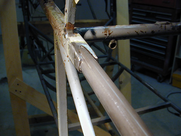
| New tubes cut to fit and tack-welded into place. The vertical tube had to be cut because it was too long with the fuselage straightened out. At some point in this glider's life it had been repaired at this location - there is evidence of weld repairs on the left side of the fuselage frame - apparently it did not get put back together straight. |
 |
| May 11 - with the fuselage aligned, jigged, braced and supported, I cut out the tubes that form the errant joint. |
 |
| Renee and I discussed this at length and we eventually decided that the bent aft frame is being caused by some stress at this joint (above). I cut the joint in two places and the frame popped apart with a bang. |
 |
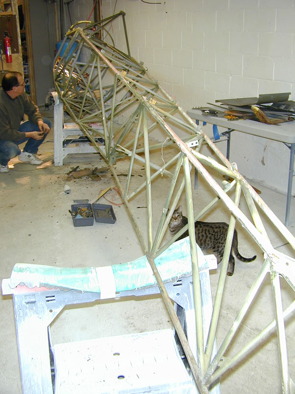
| Next problem is the significant list to port that the glider has - no idea when or how this happened, could have been the ridge accident, or maybe before, but it is certainly bent to the left! In the photo above, the glider is rolled over to the left and you can see the right upper longeron has a significant bulge at station 140. |
 |
| Easy one - all lined up with the 1X6 keeping the frame straight and tack welded into place. |
 |
| Cut the tube out and slip in a new piece of .028" thick wall 5/8" diameter 4130 steel tube (laying on the welding table in the background). |
 |
| The aft keel tube is hopeless... bent, repaired twice and now rusted through in two other locations, it's time for this piece of tin to go the way of the Dodo. |
 |
| May 6, 2003 - the nose section is complete. |
|
 |
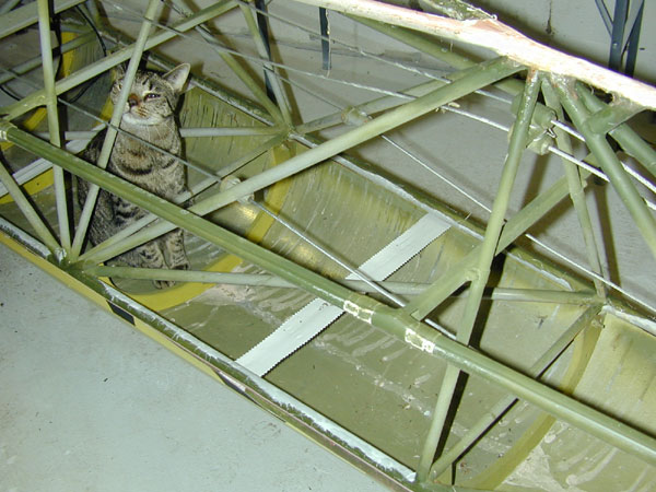
| The Tabby Cat inspects the new control stick installation for mounting and security. |
 |
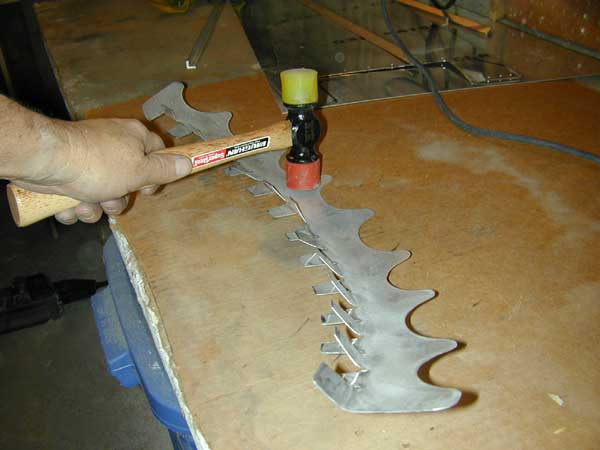
| The rudder pedals are clamped into position with the mounting tabs bolted on - then I tack weld them into place. |
 |
|
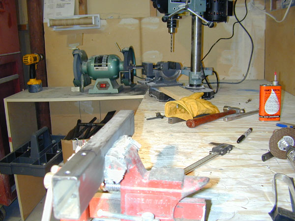
Finishing the tabs on the bench grinder.
|
 |
|
 |
|
 |
|
Drilling the big holes prior to cutting out the shape of the rudder pedal tabs.
|
 |
|
 |
|
I fabricate the rudder pedal mounting tabs from .063" 4130 steel plate.
|
 |
|
Keel longeron and hook mounting structure is finished.
|
 |
| I cut the keel longeron to length and (above) weld a section of mild steel onto the cross bars to hold the bulkhead attach plate in the proper location. |
 |
|
The skid attach plate tacked and ready for welding.
|
 |
|
 |
|
 |
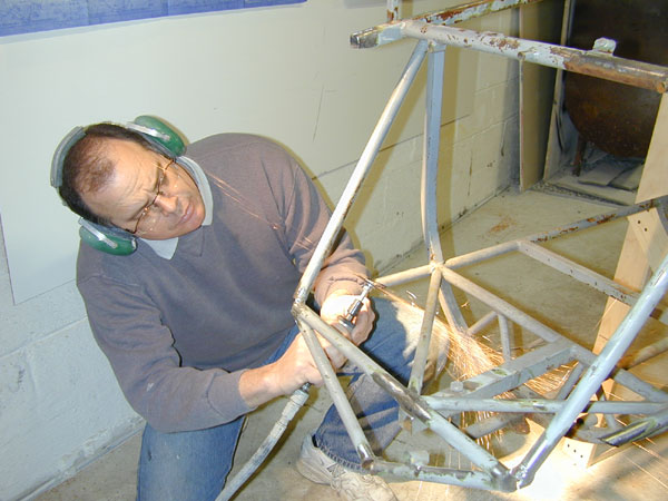
| I cut a new skid attach bracket from a piece of 4130 rectangular channel - first I drill the holes and layout the cut lines, then I cut the piece out with the cutoff wheel (above). |
 |
|
 |
|
Welding the tubes that carry the tow-hook loads to the main longerons.
|
 |
| Gas welding in the year 2003 - it's ugly, but it's solid. Gas welding takes some practice. I'm much better at TIG welding because the heat control is so easy - using a foot pedal on a TIG machine is much easier than trying to control the puddle temperature and size by varying the flame temperature and filler rod addition rate. But it's good to get back to basics. It's important to make the weld good and solid and to overheat the joint rather than under-heat - so I invariably blow through in a few places, but after I fill the holes in I know it's a good joint because the metal is certainly fused together! By the time I get done my welds will even look good! |
 |
| The welding rig rotisserie rigged up in accordance with the 1-26 Association Overhaul Manual. |
 |
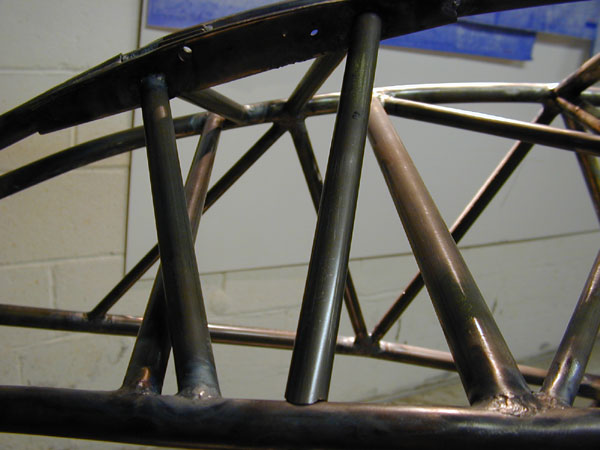
| The upper tubes are welded - now I have to locate and weld the release hook mounting structure, weld in the side braces to the keel longeron and the forward tube of the keel longeron and add the rudder pedal tabs and it's finished. |
 |
| welding the bulkhead plates onto the ends of the tubes. These plates are drilled and will be riveted to the nose bulkhead. The plastic in those fiberlock nuts vaporized pretty quickly after this photo was taken. The torch produces a 6300°F flame cone. |
 |
| I'm working my way down and around the aft side of the joint - moving much quicker now because the joint is at a very high temperature. That ESAB (Purox) W-200 torch is a fine unit indeed! |
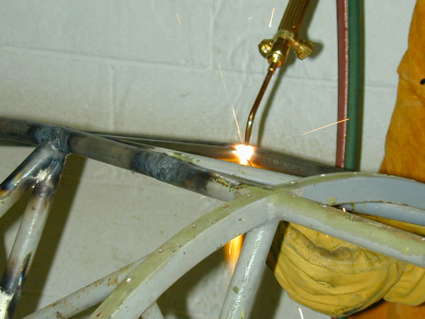 |
| I've got a nice hot, molten puddle going and I move around to the top, dipping the RG45 mild steel rod in the puddle, thus cooling the puddle and preventing blow-through, you can see how far I've backed off the flame cone because the weld joint is white hot now and if I leave the flame cone where I started, I would blow through the puddle and vaporize a nice big hole in the 4130 steel tubes. The molten puddle and weld is only a quarter inch wide - the big white spot if just the very hot tube glowing bright yellow. |
 |
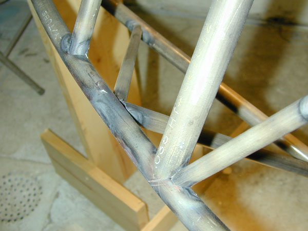
| 3 May 2003 and I'm welding all of the tubes together. The next three photos show the sequence of welding a fishmouthed tube to the large side longerons. The tube is already tacked into place. I start halfway around the tube on the forward side and will work my way up and around. You can see I have the torch in close to the joint to get the puddle started. Controlling the size and temperature of the puddle takes some practice - one needs to position the torch flame correctly and move it in and out to maintain the puddle temperature without blowing a hole in the tube. |
 |
| Bulkhead attach plates are tacked onto the ends of the fuselage longerons and I build a rotisserie to facilitate rotation of the fuselage while finish welding all of the tube joints I've created. You can see below that the tubes are all tacked in place and it's time to start welding. |
 |
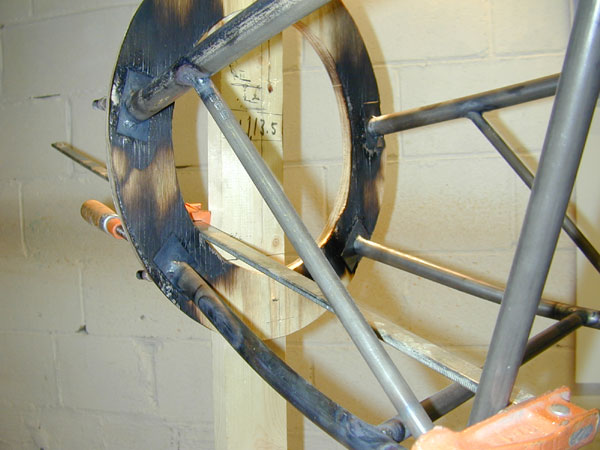
| With the bulkhead attach plates cleco'd to the bulkhead form, I tack the plates to the fuselage longerons. I did not burnt the house down, but the burning former did generate plenty of wood smoke. It's handy to have the big exhaust fans in the window - I always have them on while welding. You can see the WL 13.5 mark is centered on the bulkhead centerline and the centerline markings on the bottom face of the bulkhead former. |
 |
|
 |
|
 |
|
27 April 2003 - a close up of a joint, tacked up and ready for welding.
|
 |
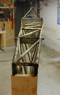
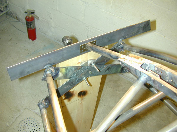
| A photo from the front. There was a lot of measuring, adjusting, hoping and praying going on during this process of lining up the four big tubes and tacking the minor tubes into place - but it worked. |
 |
| April 26 2003 - all of the tubes for the forward frame above WL 18.25 are tacked in place. I need to place the fuselage in a rotating jig to turn it over and finish tacking the lower members into place. Then I'll weld it all together. |
 |
| 19 April - below - after tacking up the forward frame structure, I place the old nose bulkhead at STA 6.00 and find that the dimensions used to jig the frame were perfect. It fits right into place - I am truly amazed! |
 |
| I'm using a Purox (ESAB) W-200 torch with forward valves - very light, nicely balanced and very controllable. |
 |
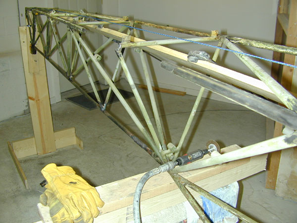
| This side photo shows how far I had to bend the lower tubes at WL 18.25 to get them to form to the correct OML (outer mold line) and meet all of the waterline, butt-line and station locations at each joint. The plans provide the correct dimensions for each joint, so it's simply a matter of assembling a tubing joint, clamping it in place, heating the big tubes and bending them up with the big clamp until they meet the station called out on the drawing. Compare the bend in the lower tube with the photo below this one (from April 14) and note the burn marks in the wood from heating the tubes. |
 |
|
 |
|
 |
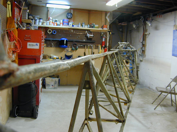
| 14 April 2003 - I continue to square up, locate, cut and fit tubing to the forward fuselage frame. |
 |
|
 |
| 12 April 2003 - The longerons are held in the proper locations using the 1X3 poplar boards. The remaining tubing may now be cut, assembled and tacked into place. |
 |
|
Cutting a tubing joint in one of the cross-pieces using the joint jigger.
|
 |
|
 |
| Renee takes a photo of me cutting the 30° scarf cuts needed to splice the new tubes into the old tubes. I'm using an internal splice tube to allow for a nice fair on the outside of the tube where the fabric will rest. The dimensions of the splice are calculated and laid out in accordance with the AC 43.13. I make sure to align my eyes perfectly in line with the cutoff wheel so I don't miss any of the sparks. Squinting helps keep the sparks and metal pieces from going directly into my eyeballs ;-) |
 |
|
I install the four main longerons in order to start locating the rest of the tubes.
|
 |
|
New tube fits nicely in place.
|
 |
|
Knocking the old tube pieces out with a chisel.
|
 |
| I grind all of the weld material from the main longeron tubes so I can fish the old broken tube pieces out of the I.D. of the square tube. |
 |
All the damaged tubing is cut away. I'll finish these joints by grinding away carefully all of the remaining tubing pieces and weld material - leaving on the good, un-damaged tubing onto which I will weld new 4130 steel tubes after they arrive from Aircraft Spruce tomorrow.
|
 |
| 9 April, 2003 one of the upper longeron welds after clean-up. This is gas welding from 1955. |
 |
| With the fuselage leveled laterally and longitudinally, and then jigged into place - I locate the zero stations and waterline. The right face of the horizontal 1x4 is the zero butt line, the bottom edge is WL 0.0. The bulkhead is temporarily beat flat and attached to STA 6.0 at WL (waterline) 13.5. The instrument panel steel tube that the 1x4 is notched into is bent aft about 1.5 inches and will have to be relocated forward where it belongs. I think it moved aft when the nose hit the dirt. |
 |
| Damaged tubing cut away. Nose cone came with the other parts from the insurance company - it's very flat. |
 |
| Using the drawings hanging on the wall, I will continue to plot and jig all of the station locations for the damaged tubes. Next I'll cut off the damaged tubes and clean up the joints, then I'll cut new tubes and start to fasten them to the wood framework that will hold them in the proper location for tack welding. Once the tubes are tacked in place, the framework will be removed and the welding completed. |
 |
|
 |
|
 |
| Fuselage in the jig, box of removed part underneath. Lots of cleaning, stripping, sandblasting and painting to do on the detail parts. |
 |
|
Fuselage stripped of all parts ready for clean-up and tube repair.
|
 |
| I sanded down the skin to remove all of the paint and Polybrush and fiberglass residue and to reveal any hidden rivets prior to drilling the last of the rivets out and removing the cockpit skin. This skin is thick and heavy, I estimate it weighs over 15 pounds. |
 |
|
Cockpit skin removed. Not too much rust on the faying surfaces.
|
 |
| Could be some bad places here, but maybe not - I'll know after I've cleaned it up. It looks worse than it is in this area. Other areas don't look bad, but the tubes are rusted through. |
|
| After removing the 1970's era steering wheel cover, it is obvious that the cover has been in place since the 1970's!! The control stick where the cover was is very badly rusted and will have to be replaced. I suppose all those years of sweaty palms filled the steering wheel cover with a nice saline solution that ate through the steel tube very effectively. |
 |
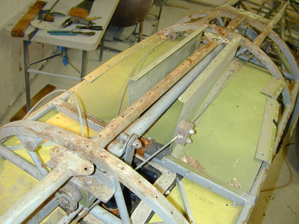
| I'll be able to salvage all of the tubing aft of STA 22 - just forward of the elevator bellcrank in this photo. The bulkhead material is 24SO, heat treated after forming to 24ST, or 2024-T42 to you youngsters out there. |
 |
| Fabric removed... cats are bored now and head off for a nap. |
 |
| 5 April 2003 The wheel box looks good, some rust in the tubes underneath it, but nothing too bad. Most of the rust damage is at the aft end of the fuselage, so this won't be too bad. |
 |
|
 |
| Skid removed, last bit of the fabric pulled up and rivets drilled out of the left side. Below - I had to cut the skid and skid plate into pieces using a cutoff wheel and handsaw for the wood. That wooden skid was actually a piece of plywood someone cut to length. It had long since rotted and sawing right through it took about five seconds. I'll replace it with a nice piece of ash - strong and light. |
 |
|
 |
| TC inspects the damage to the tow hook structure to determine what can be salvaged. The release arm is bent, but maybe it can be repaired. We removed all of the stuff hanging off the nose this afternoon including the release mechanism, spoiler controls, rudder and elevator cables, nose bulkhead, etc. |
 |
| The turtledeck is off, the wheel and wheel well box removed and side stringers are removed. There are a number of sleeve repairs on the keel tube, I'll be assessing the amount of keel tube I'll have to replace, maybe most of it, that will remove some of the existing tube repairs as well. |
 |
|
The turtledeck comes off.
|
 |
| The cockpit skin covering will be removed by drilling out the rivets attaching it to the steel frame. |
 |
|
 |
|
Percy is intrigued by some detail on the turtledeck attachment.
|
 |
| Inspection completed, the Tabby Cat departs the scene to file his report. He says August 1st is wishful thinking - he's usually right. |
 |
|
 |
|
 |
|
 |
| No drain holes were placed anywhere in the bottom of the fuselage and this is the result. As reported by TC, we have rust damage on some of the aft tubes and two tube splits. We'll be splicing in some 4130 before this job is done. Below - one of the splits. |
 |
| Yuk! Here's why fabric condition does not really tell the story, I think this glider was recovered in 1995 or 1997 - relatively young fabric in very good condition, but the moisture in the bottom of the vee has done some damage - as you will see below. |
 |
| Wheel well area is not too bad. That tire must be at least 10 years old. |
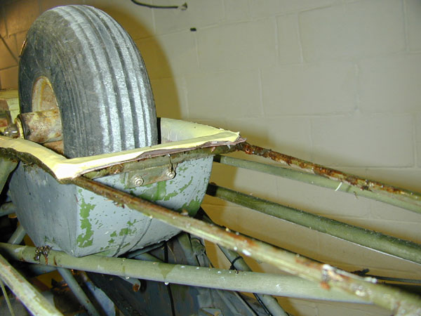 |
| Fabric removed from around the wheel well area and flipped upside down to show the accumulation - again no drain holes and some rusting. This glider sat for over a year since the accident and sitting outside in the snow for the past 2 months hasn't helped. |
 |
|
 |
| Another rusted and split tube at the aft end of the fuselage. |
 |
|
31 March - Renee takes photos of the glider so we will remember how to put it back together. Tabby Cat hops into the cockpit to begin his inspection.
|
 |
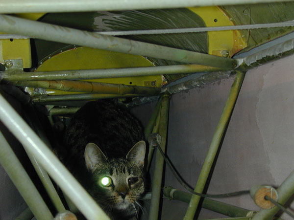
| TC is well-equipped with night vision for the detailed interior visual inspection. Note the attachment method of the aluminum turtledeck. |
 |
| Fiberglass fairing comes off. |
 |
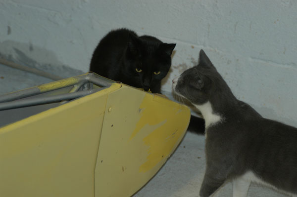
| Percy (in black) and Pippin are wondering how the Tabby Cat is going to get out of that tight spot he's in. |
 |
| William rarely comes into the glider parlor, but cannot resist this stinky, rotting treasure trove and soon discovers the Tabby Cat in the tailcone. |
 |
| The fabric tapes running across the turtledeck kept it from springing out, essentially kept the aluminum top fair with the fuselage. When I cut those fabric tapes, the turtledeck sprung out away from the steel fuselage frame. |
 |
| With the Tabby Cat pushing and me pulling, the fuselage fabric yields easily. Obviously this fabric is Stits Polyfiber as evidenced by the pink color of the PolyBrush. |
 |
| I get some help with the rudder cable removal. |
 |
|
 |
| After photos are completed documenting the exterior condition, I begin to remove the covering. |
 |
| Here's the reason I suspect poor paint preparation. The aircraft was recently re-painted and the paint is flaking off the aluminum surfaces because the surface underneath was not prepared to accept the new coat of paint. You can see the shiny, waxed surface below the layer of paint I am pulling off! It was not sanded, perhaps even had wax residue remaining - certainly not conducive to a good paint adhesion. |
 |
| The tail is OK, but the rudder appears to be bent, or the fabric over-tightened. The paint is flaking off the elevator, so they'll get recovered. I never did like Ag-Cat yellow - looks like Faded Yellow to me. The seal is cut to facilitate removal of the rudder. Renee is helping and she removed the rudder while I removed the seatbelts. |
 |
| The horizontal stab fabric is in good condition, it's Stits Polyfiber, only about 3 years old. The paint is flaking off due to poor preparation. |
 |
| A new skid, all new instruments and instrument panel, a new hook release arm, and a few other things. |
 |
| Minor rusting, not bad really. |
 |
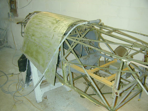
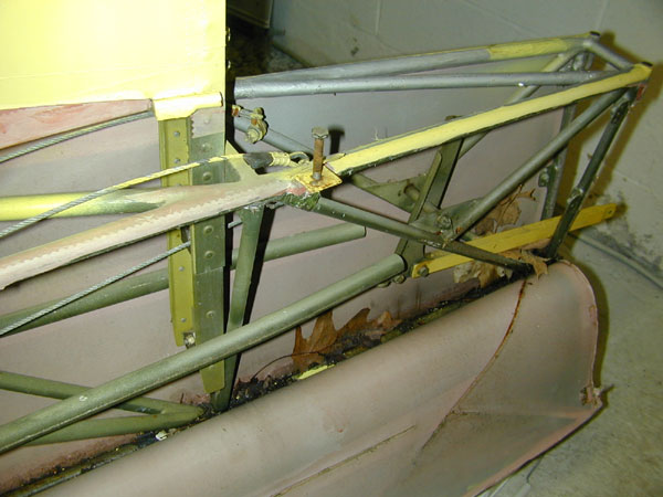
| View of the aft fuselage interior, the fabric will be removed and the frame is going down to bare metal. |
 |
| Another problem is a bent fuselage - compare this photo with the photo below. The fuselage is obviously bent to the right looking aft. How and when this occurred is unknown, could have happened in the accident, but I don't think so, there is no wrinkled fabric or aluminum, so I think it's been bent for some time. I shall have to straighten it out. |
 |
|
 |
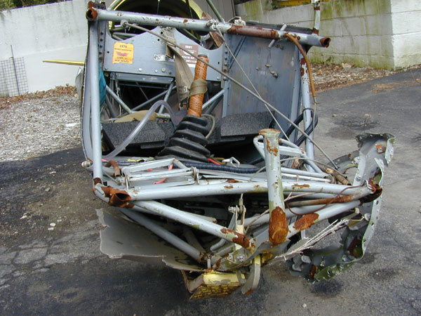
| Here's the biggest chunk of work ahead - rebuilding the nose section damaged when it hit the ground after clipping the tree. I'll need most of the parts in this picture - some tubing and a new nose cap. |
 |
| March 29, 2003 - ready for disassembly. The canopy and turtledeck were removed and are being sent to me by the insurance adjuster - apparently they are in good condition. The instruments have all gone missing. |
 |
| this is going to be the biggest challenge, I have all of the fuselage drawings needed to fabricate new tubing parts and weld them into the correct positions. Fiona stands guard in the background. Extension cord on the ground is charging the batteries in the Nimbus in anticipation of a weekend day without rain. |
 |
|
|
|
|
|
|
|
|
|
|
|
|
|
|
|
|
|  |