|
|
| ELT installation |
Go here for Towhook replacement and here for oxygen system installation |
2 December 2005 - It snowed last night here in Bonney Lake, WA - about 4 inches, first real snow since February 2004. Today UPS will deliver my new AmeriKing ELT that I purchased from Paul Remde. Only $200 -I figured it was worth the peace of mind after much thought about all the opinions expressed on RAS and the SRA poll. |
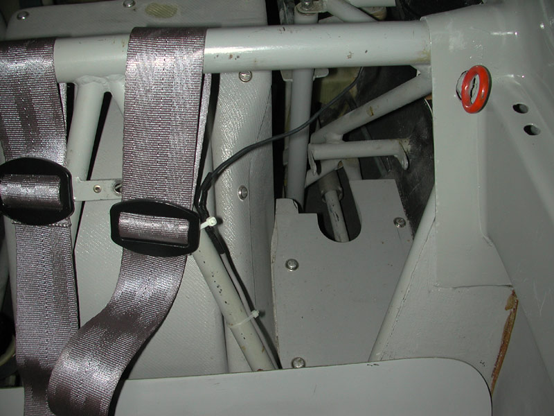
| I've scouted a location for the ELT itself, there is a handy location on a piece of plywood that exists to the left of the main wheel housing. I measured the available space and found that the AmeriKing will fit nicely. I plan to install the antenna on the forward bulkhead, possibly under the glareshield as Roy Bourgeois did. I don't have photos of the antenna installation in his Nimbus, but I have an idea of how it can be accomplished. |
 |
While the Nimbus is Experimental-Exhibition and 14 CFR Part 43 is not applicable, I am going to pretend it has Standard airworthiness so as not to mislead anybody reading this and working on a Standard airworthiness glider. (Part 43 is mostly not applicable, maybe - don't be fooled by 14 CFR 43.1! Read your Operating Limitations about complying with 14 CFR 43.3 if you have the newer Experimental Ops Limitations) Doing a bit of research, I've determined from a plain language reading of 14 CFR Part 43, Appendix A that the installation of the ELT, its antenna and control panel is a minor alteration. You may read the definition of major alteration for yourself here: Appendix A The rule says any alteration that is not considered major (per Appendix A) is a minor alteration. (Same for major and minor repairs) So, 14 CFR Part 65 states that I, as an A&P certificated mechanic, may perform this minor alteration and sign it off in the aircraft logbook. (Also revise the weight and balance accordingly) I must install the ELT in accordance with manufacturer's instructions and I plan to use the guidelines and clever techniques outlined in Advisory Circular 43.13 and Advisory Circular 91-44A available here: Advisory Circulars Just type 91-44 or 43.13 in the search box and they come up. If I was not an A&P, 14CFR Part 43 does not grant me the privilege of performing a minor alteration using only my private pilot certificate or my good looks (in the case that I did not have even a private pilot certificate). If you can find an A&P willing to supervise your work, you contest pilots may install an ELT as long as you are under that A&P's supervision and he /she makes an entry describing the alteration in the aircraft logbook. Another good thing to remember is the annual testing and inspection requirement for ELT's installed in aircraft. I know there may be some disagreement and discussion on RAS on the need to comply with 91.207(d) for an aircraft that is not required to have an ELT installed, but I plan to do the inspection and test just in case one of my FAA friends shows up and starts asking test questions. Better safe than sorry because you're under the lights in a conference room at the FSDO. |
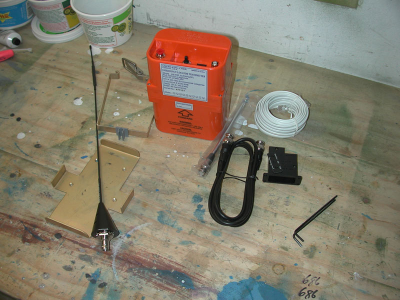
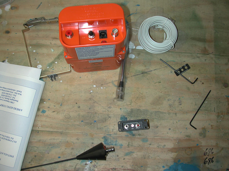
| Below - 2 December - The ELT arrived this evening and I really like this unit, specifically because everything you need is included for about $200. Pretty good deal if you ask me; not to mention that it operates on D cell batteries! Years of dealing with model-specific batteries causes me heartburn just thinking about the hassle of ordering the special batteries and the cost. |
 |
Below - taking Roy Bourgeois' idea, I check the antenna for fit under the glareshield. This will be easy. I don't believe I can install the antenna aft of the cockpit because the fuselage is all carbon fiber back there and I'm afraid the carbon-fiber will mask, or seriously diminish the signal from the ELT. It may not (not sure anyone has actually tested this) but I think it's a reasonable assumption that having the antenna up forward shielded only by Plexiglas and the Kevlar/fiberglass cockpit will certainly allow better signal transmission. |
 |
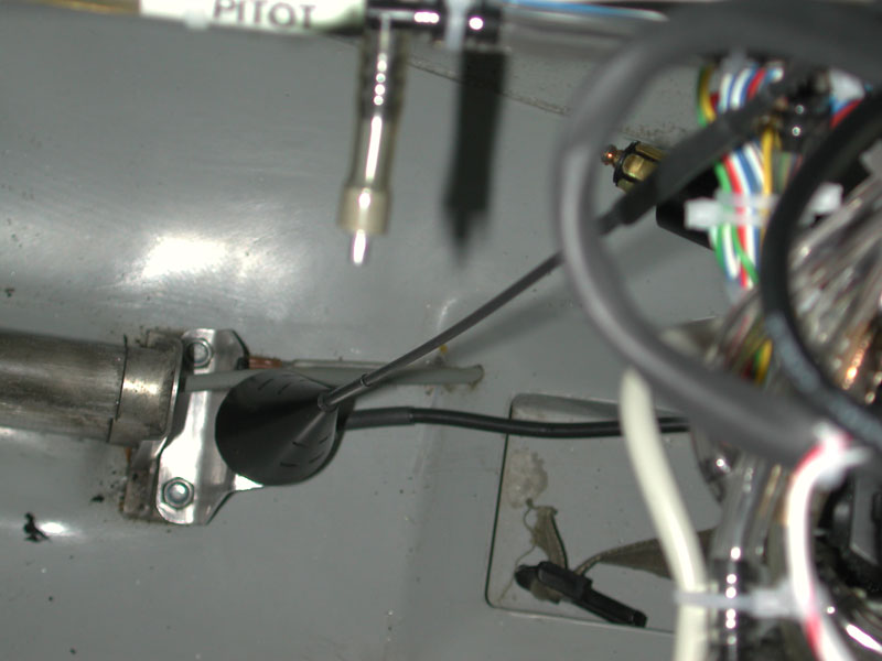
| Below - I may install the antenna facing aft, but either way I may need a longer coax, the six foot unit supplied appears to be short by about 10 inches. |
 |
Below - The ELT mounting bracket is a perfect fit. |
 |
| Below - This unit has a remote control panel connected to the ELT by the phone cable shown in the photo. Another nice feature is the microphone jack on the unit allowing voice communication on 121.5 in case an emergency transmitter is needed. |
 |
Below - 3 December - It's cold in the garage, maybe 37° and I've encountered a small setback: the ELT installation manual requires the antenna to be installed within 20° of vertical, so I cannot install the antenna horizontally as I had planned. Instead, I decided to fabricate a mounting bracket that I attached to the rudder pedal assembly aft mount bolts. This was actually a good thing to do because the rudder pedal mount is grounded to the fuselage and that will provide the required ground plane - I wasn't sure what I was going to do about a ground plane in the horizontal installation, but now that problem is solved. |
 |
| Below - Mount bracket fabricated from .050" thick 2024-T3, a portion trimmed on the side opposite of this view to allow the rudder pedal adjuster cable run past the bracket, you can see the black tape I used to prevent abrasion to the rudder pedal adjuster cable. Because the BNC connector is very close to the floor pan of the cockpit, I will use this 90° BNC connector, removed from the radio coax when I installed the Becker, onto the end of the ELT antenna coax. |
 |
Below - antenna bolted into place, coax connected, ready for test. |
 |
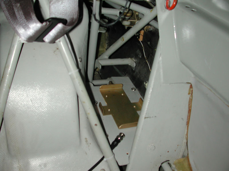
Below - ELT mounting bracket installed on the shelf behind the seat. |
 |
| Below - shelf screwed back down, ELT installed and since it was 3 minutes after the hour, I thought I would see if it works. I tuned the Becker to 121.5 and turned the ELT switch on and voila! the red LED light illuminated and that familiar squeal sounded very nice. I clip the portable telescoping antenna to the side of the bracket and this part of the job is done. |
 |
| Next I will run the coax under the seat pan and install the 90° connector on the antenna end, then install the remote switch module in the instrument panel - after my fingers warm up a bit! |
 |
| Below - 4 December - I have to disassemble the remote module to install the optional, vertical faceplate because I plan to install the remote module vertically under the wing drag meter. |
 |
| Faceplate installed, ready to make the panel cutout and install the remote module. Interesting to note that the remote module must be installed with this ELT in order to comply with the installation requirements of TSO C-91a. So, per the manual, this unit is not optional - it must be installed where the pilot can reach the buttons and see the LED indicator. |
 |
Below - Making the cutout in the panel and throwing the tennis ball for Samson. Failure to throw the ball in a timely manner results in a gentle, but firm nudge under your elbow by a big wet nose, sure to throw off any complicated and critical measurement or drilling I may be doing at the time. Best to keep that ball in the air regularly! |
 |
| ELT remote module installed and it's 2 minutes after 4pm - time for a final test. Next I'll finish the drag meter tubing renewal and do a final inspection, lube, cleanup and re-assemble the cockpit. The cockpit reconfiguration is almost complete. |
 |
| Time to call it a day, but Samson is eyeing my new pitot tube and air vent cover, donated by my neighbor Lee Lepper. I weighed the ELT, it weighs 46 ounces, so I'll recalculate the weight and balance and update the logbook with the new installation. I suspect the CG change will be negligible or nonexistent since the ELT is sitting right at the CG. |
 |
| March 9 2003 - John Murray of Eastern Sailplane sent me an overhauled Tost release. The old release was original and after 20 years was showing signs of wear. The Schempp-Hirth manual states "remove the three bolts and remove the tow hook". That's a German version of a joke. Took a full hour in the freezing cold in January to pry that release from it's well-secured mounting. The brackets were epoxied in place and the brake master cylinder was fiberglassed over the top of the release mounting bracket. Once all the brackets were removed, the release would still not come out until I had ground away some of the hole through which the round release cage protruded. |
 |
| William the One-Eyed White Cat is totally un-impressed, he thinks the wheels are much too small for the soft grass runways here in the Northeast. He can't wait for spring to arrive - the glider parts depart the basement and the mice start to arrive - much more interesting and a lot less stinky than gel-coat and acetone! Note the barn door on roller that swings closed to allow egress in and out of the door to the driveway and keeps cats out of the glider repair area. |
 |
| The release mounting brackets are epoxied into place and the nuts run home onto the bolts with the assistance of Renee holding the wrench on the forward facing bolts that are accessed from the wheel well. |
 |
|
Installing the brake master cylinder mounting bolts.
|
 |
| 8 month old Pippin cruises through the shop to "see" what's new. He knows the wings are gone, and is trying to determine the dimensions of this strange new inhabitant (the fuselage). Because he's totally blind, he gets around on Sonar and memory. Moving the wings out and the fuselage in means he has to bump into the fuselage for a while until he remembers where it is and where it goes. It's incredible that within 24 hours, he's hopping into the cockpit and running up and down the interior of the fuselage. He simply follows one of his buddies that has one or more eyes. |
 |
|
The removed release showing 20 years of wear and tear.
|
 |
| Latest updates for 2003 are complete - iPaq being charged by the low-drain PS-5a, SN10 connector installed, LED Flap Position Indicator installed and the Tabby Cat is behind the radio, completing his inspection of the wiring and making sure all the metal savings are cleaned up prior to giving me the OK to close. |
 |
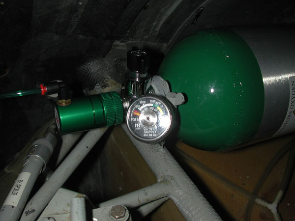
| 2/15/2004 - New M&H oxygen system installed. Aluminum 647 bottle with EDS delivery system. I chose the big bottle because it fits the existing aft clamp mount - 5.25" diameter. |
| I had to modify the forward mount slightly to accommodate the short neck of the bottle and not interfere with the valve body. I also installed a brass 45° elbow to help the mount clear the gauge and it also points the gauge at the fuselage access panel so checking the oxygen pressure is very easy. |
 |
|
Detail of the forward mount, gauge and regulator.
|
 |
|
Here you can see the gauge through the fuselage access panel.
|
 |
Below - Oxygen controller and tubing installed in the forward cockpit. |
 |
| February 22, 2004 was a beautiful Sunday - preceded by a beautiful Saturday! 65° F outside and a great day to do the annual condition inspection, fix the ballast valve leaks, spruce up the trailer, fix gelcoat dings and generally just soak up the sun. |
 |