|
Instrument Panel and Cockpit |
For the latest update - go here. |
23 October 2005. Below I decided to make a new panel to move the radio knobs closer to my fingers. I plan to modify the panels to have the top row of instruments/components that require adjustment during flight closer to my hands so I can reach them without leaning forward against the harness. |
Before |
 |
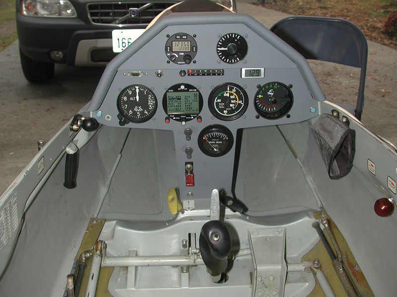
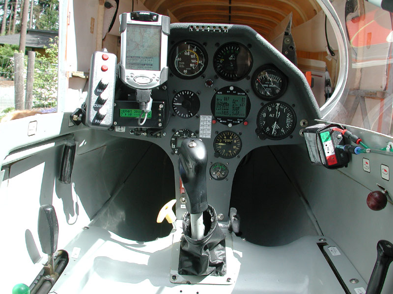
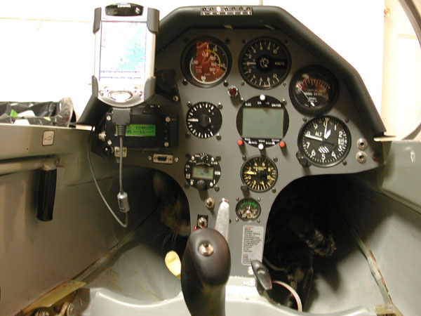
Above - 23 Oct 2005 - the existing situation. Filser ATR-57 radio removed, new digital voltmeter placed poorly over the old analog voltmeter hole, vertical card compass in a magnetically dirty location, empty holes left over from headset jacks and charging receptacle. Time to move the furniture around a bit. I think I want the big instruments all lined up even with the SN10b in the second row - Sage and ASI centered, altimeter to the right, where it is, and SN10b to the left of the ASI (the ASI will be where the RAZ meter is now). I'll install the radio above the SN10b and the RAZ above the altimeter. Volkslogger between them... maybe. |
After |
 |
Below - panel removed. |
 |
 |
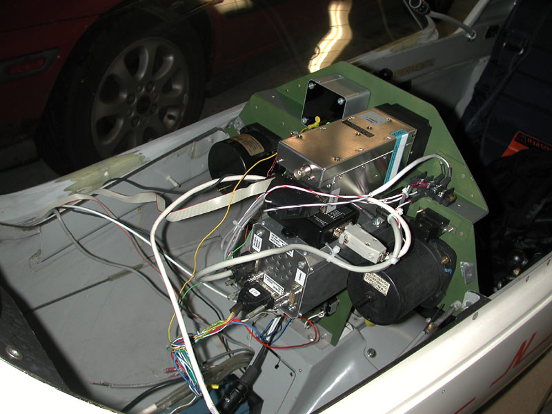
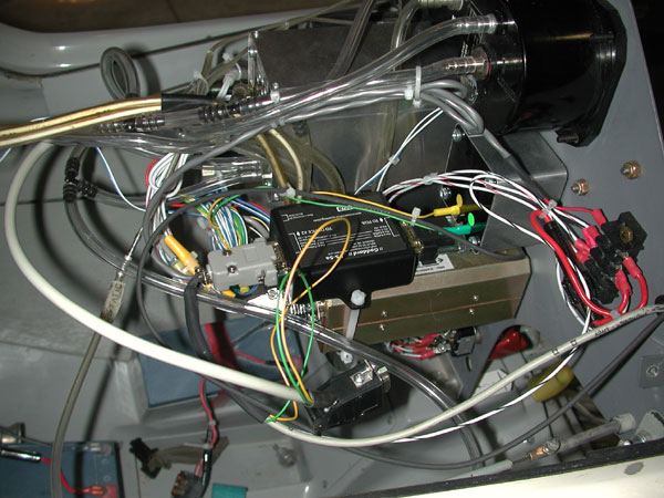
Above - the back side could use some tidying up. |
 |
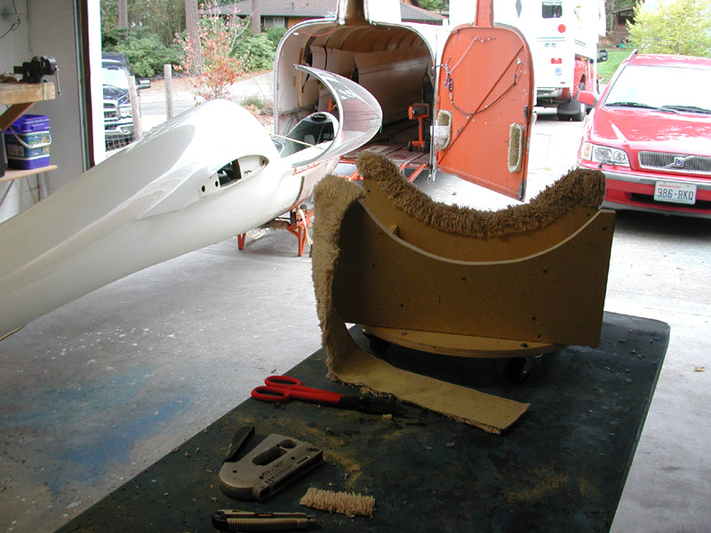 |
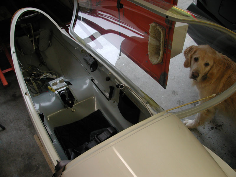
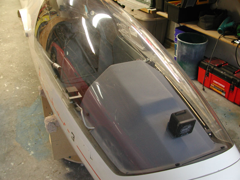
October 28, 2005 - 2 years ago today we were staying in a motel in Rawlins, Wyoming with 5 cats, a Golden Retriever, the Red Volvo and a Penske truck containing all our earthly belongings. That seems so long ago. 038 was sitting in Dave Piotrowski's yard. Life is almost completely normal now. Above - I built a cradle for H4 with casters so I can get it off the trailer and move it around the garage easily during the cockpit reconfiguration. |
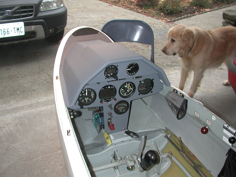
Below - the big dog wants to play catch with his ball. I am not interested. |
|
Below - the shelf to the side of the main wheel housing is a perfect location for an ELT. |
 |
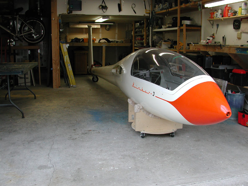 |
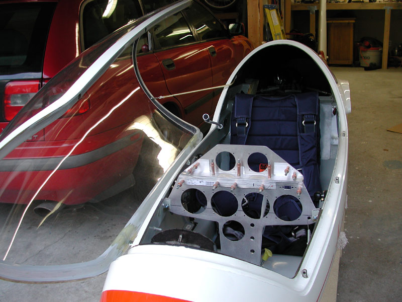
Above - the Nimbus sits on the cradle, just behind the nose you can see the 2 foot square piece of 2024-T3 aluminum, .090" thick for the new instrument panel. Obtained from On-lineMetals.com in north Seattle. Same place I found the brass rod for the aileron mass balance when I lived in Connecticut. |
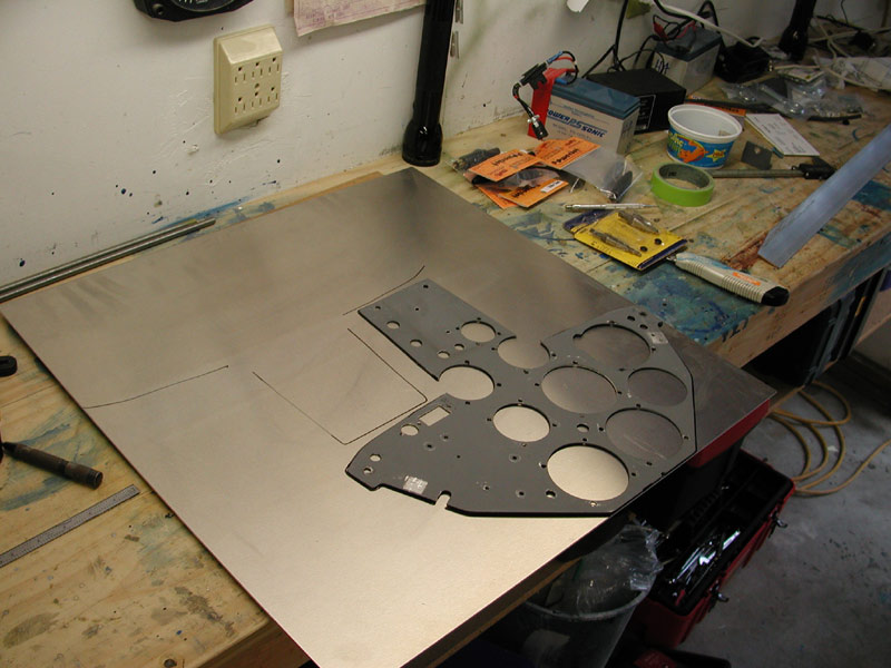 |
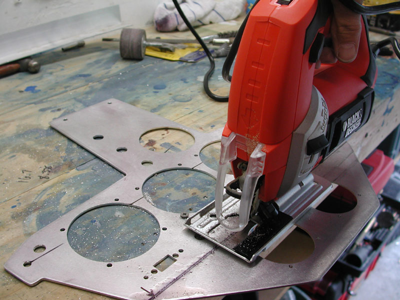
Above - I can get two panels out of this piece with very little offall if I change the radius of the leg cutouts. Below - I cut out the panel with a metal blade in the jigsaw. Hearing protection is very helpful during this part of the procedure. |
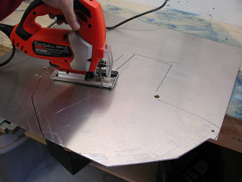 |
Below - Holes drilled and marked, I clean up the outer profile with a hand file. |
 |
Below - test fit. More modifications to come before I cut out the instrument holes. Note the large radius in the leg holes is gone, less space required with the new layout. |
 |
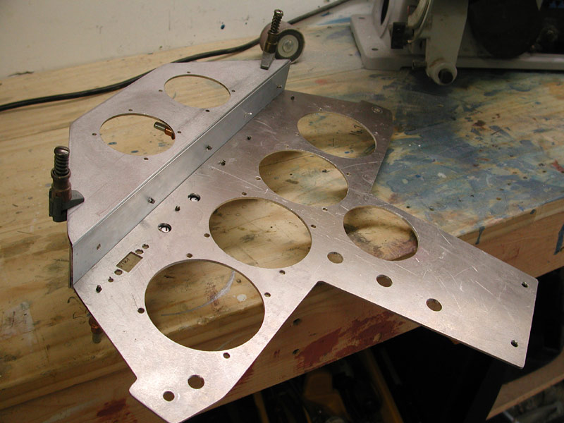
Below -October 29, 2005 - the layout and cutting begins. |
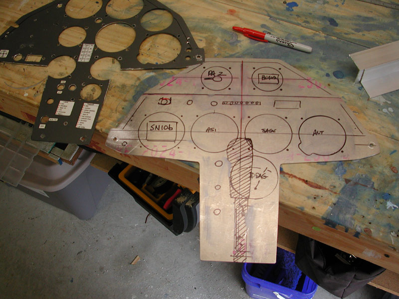 |
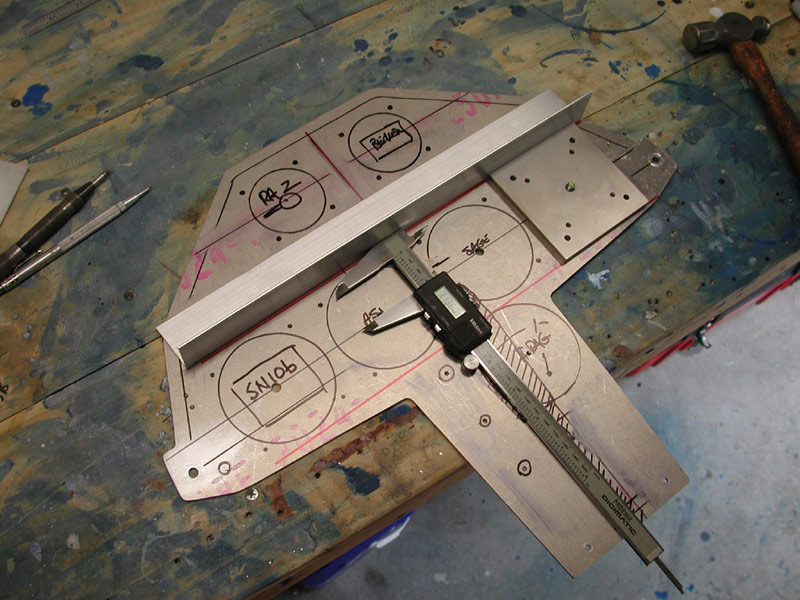
Below, I use an instrument hole drill jig to drill the instrument screw holes prior to cutting the large round hole cutouts. The pilot hole in the center of the instrument holes are drilled to .246" to accommodate the AN4 bolt that fastens the drill jig in the proper location. I use the calipers and a straight piece of angle to get the drill jig plumb and level. I do a lot of eyeballing as well. As I have said on this site before, the eyeball can detect out of plumb very quickly. |
 |
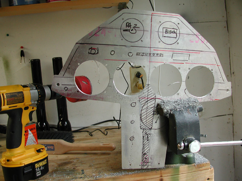
Below - All instrument holes drilled, all pilot holes for the miscellaneous items drilled and it's time to cut the 3 1/8" holes with the hole saw. I use a solid Milwaukee holesaw from Mcmaster.com. |
 |
Below - Once all of the holes are cut and the switch and circuit breaker mounting holes are drilled with the Unibit, I cut the panel in two in preparation for moving the radio mounting holes two inches closer to my fingertips. |
 |
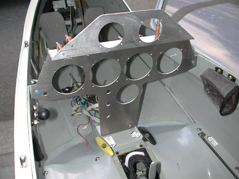
Below - Angles shaped, drilled and Cleco'd into place. |
 |
Below - Trial fit, parachute and backrest in place to check to see if I can reach the panel. |
 |
 |
Below - some minor trimming will be required to fit the hood, otherwise it's looking pretty good. |
 |
Below - I have to re-install all this stuff and a new Becker AR 4201 as well. I ordered the radio from Paul Remde this evening, should be here by next weekend. |
 |
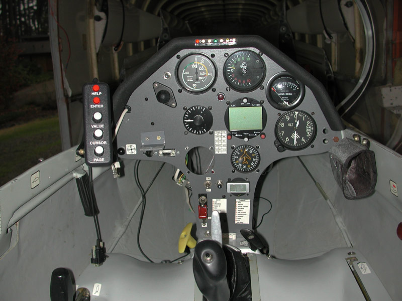
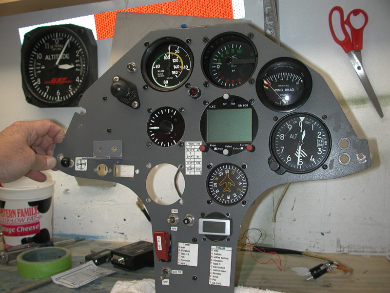
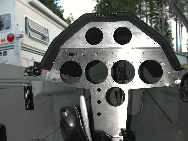
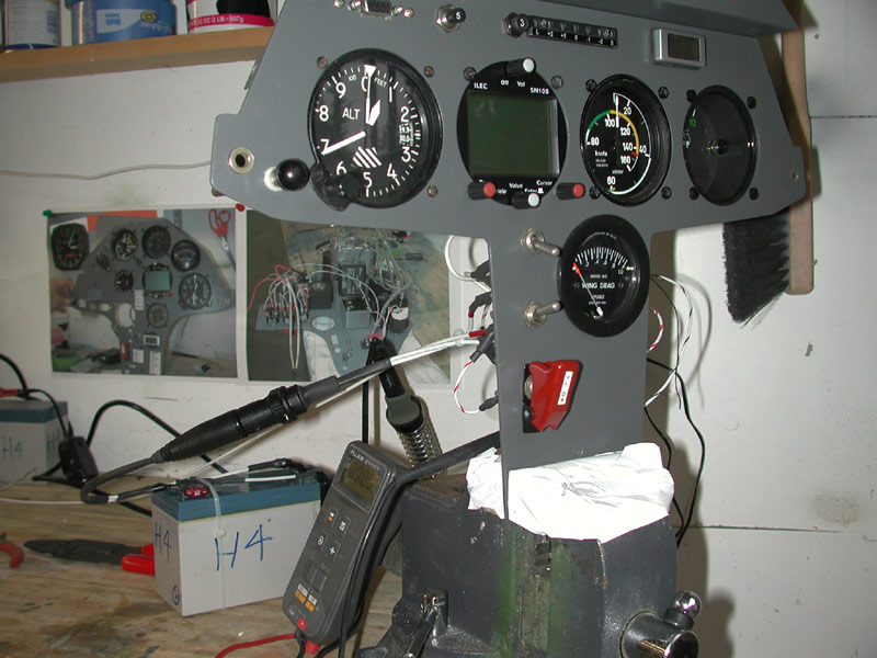
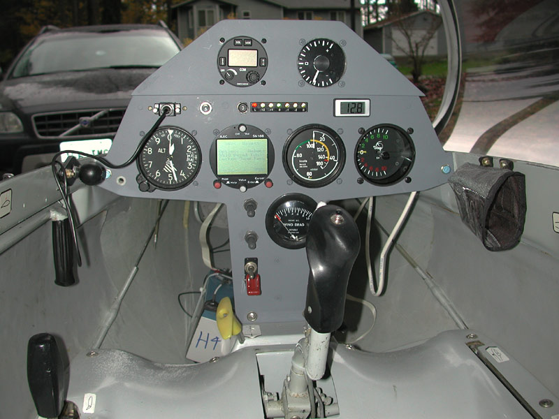
October 30, 2005 - The panel goes back in with instruments for trial fitting. |
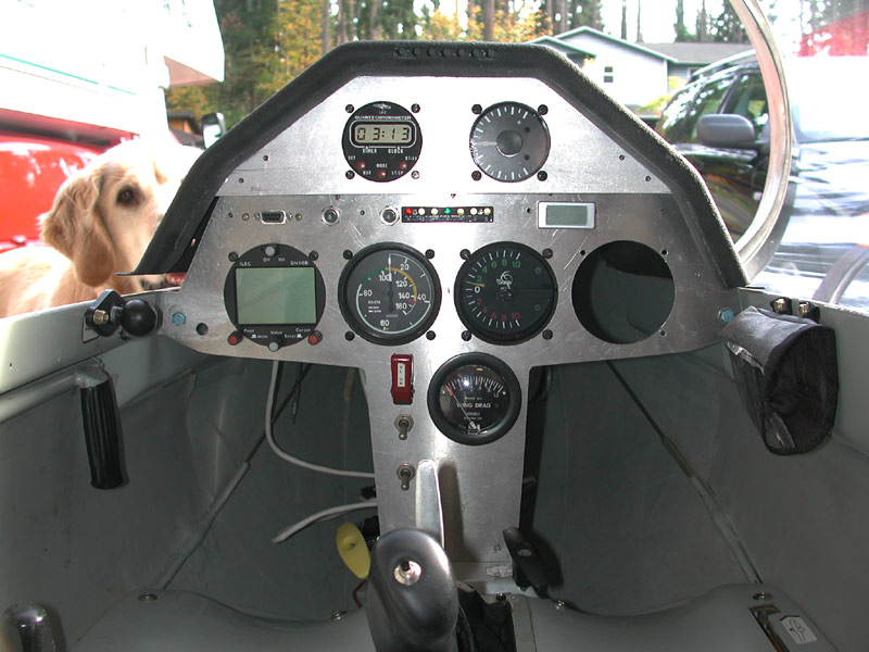 |
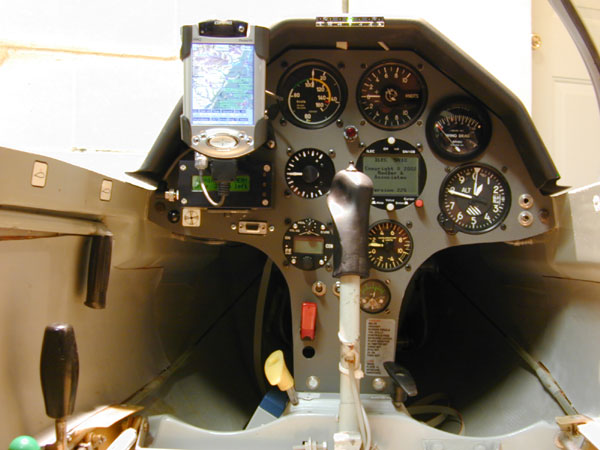
Above and below - While mowing the lawn this afternoon, I decided I wanted the altimeter on the left, the ASI where it is in the photo above, the SN10b where the Sage is and the Sage to the far right. The Becker AR4201 will go into the hole where the clock is and the clock disappears. The Volkslogger will mount to the right hand canopy rail and the iPaq may not go back in, not completely decided on the iPaq yet - I'll see how it goes. The SN10b remote goes back in where it was and it plugs into the DB9 just above the far left hole where the altimeter will be. The guarded switch is for the Volkslogger (guarded so that I do not inadvertently switch it off). The next switch down is three-position, up for forward battery, center off, down for aft battery. The bottom switch is the bus tie that ties the two separate battery busses together. This allows me to isolate a battery, or isolate a bus. The radio runs off one bus, the SN10b off the other bus and the Volkslogger/iPaq/Goddard PS5a runs off either/both. Digital voltmeter to the right of the flap position indicator. I moved the flap position indicator off the glareshield because it was a pain to have the glareshield connected by the two cables each time I remove it to change out the batteries. The dragmeter goes down below since I rarely use it, only when shifting gears. |
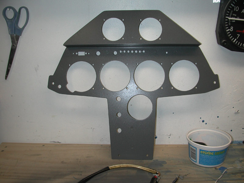 |
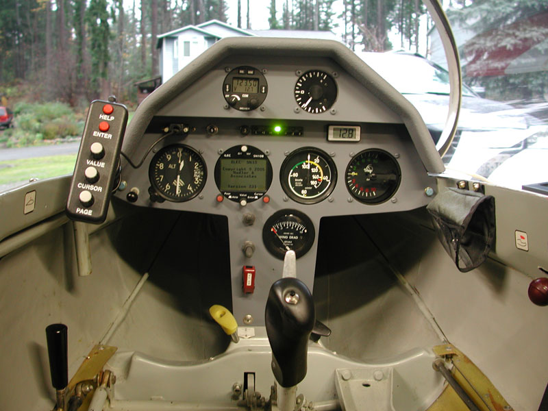
Above - riveted all together and painted, ready for electrical refurbishment. |
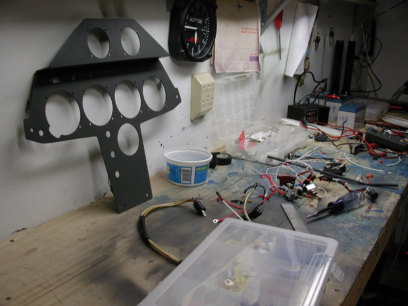 |
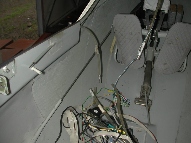
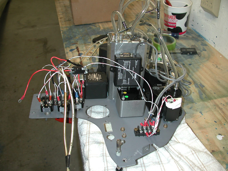
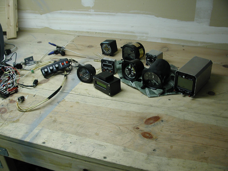
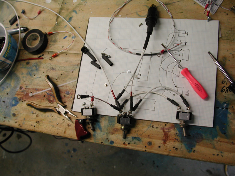
Below - November 3, 2005 - I rebuild the 12VDC power wiring with new wire, AMP connectors, Powerlet plugs and insulated heat shrink for an environmental termination. I used 12 AWG wire for the battery connections and 18 AWG between the switches and fuses and terminal blocks. Instrument and radio wiring is 20 and 22 AWG. |
 |
 |
Above - test-fitting and wiring and terminated all day long. |
 |
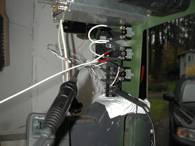
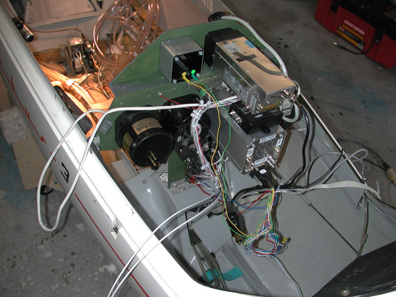
Above - November 4, 2005. Time to power up and test the power system. I have two batteries running to a DPDT, center off switch so I can select either batter to power the main bus. I have a bus tie switch to tie both busses together. I have an isolated Volkslogger switch running hot off the forward battery and it can be power by the aft battery through the bus tie. |
 |
Above, November 4, 2005 - I smoke test the new Becker AR 4201 and the SN10b. Works fine first time. All the smoke remained inside the instruments where it belongs. |
 |
Above - some tidying up to do and some radio connections still to be made. I still have to final paint the front face of the panel a lighter shade of flat gray. |
|
|
|
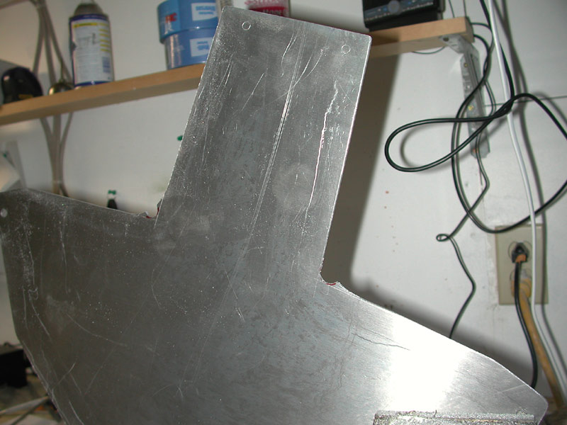
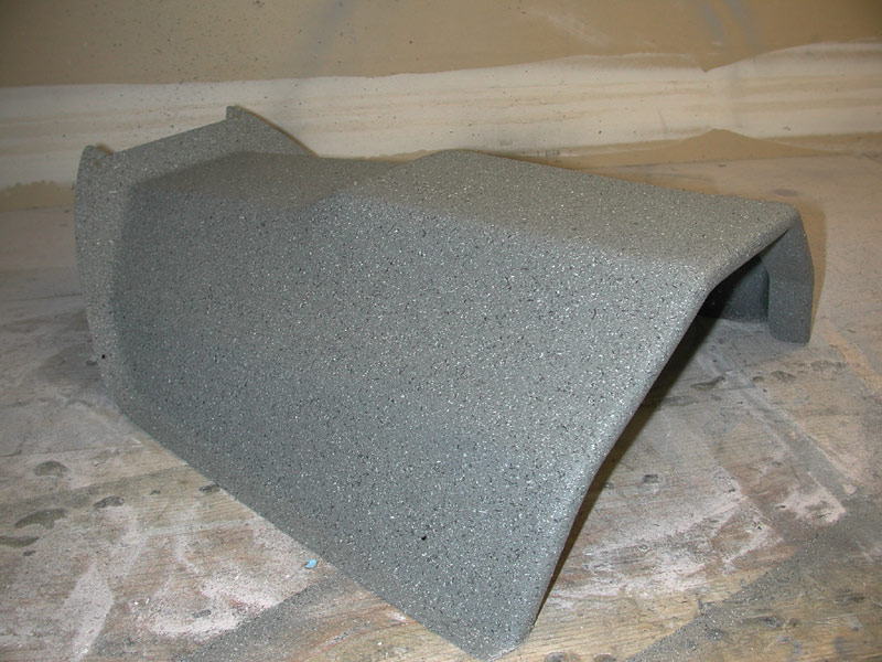
5 November 2005 - Below - I have to modify the glareshield to accommodate the new radio. |
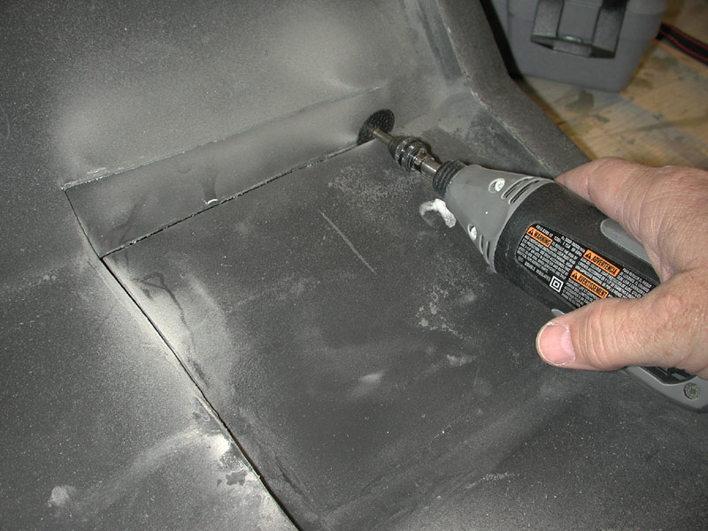 |
Using the Dremel cutoff wheel I chop the glareshield in a few places and then cut out a large section of the top. |
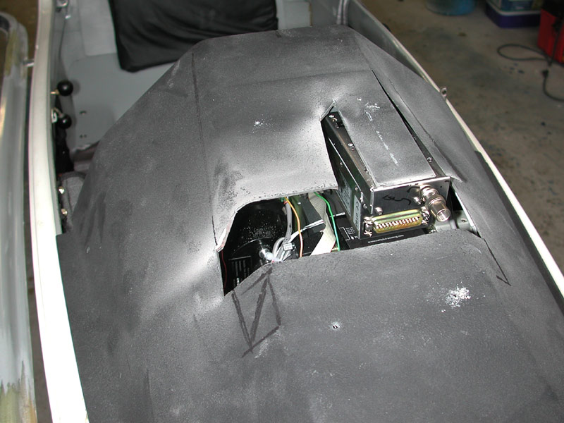 |
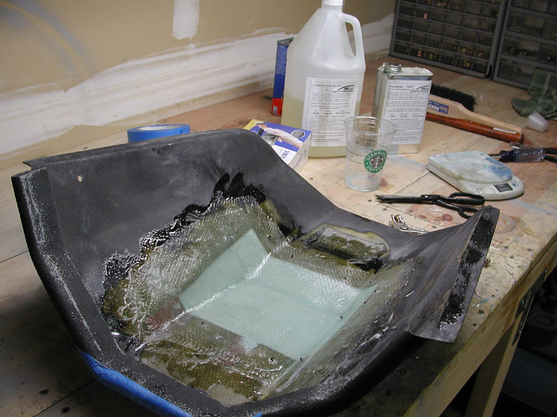
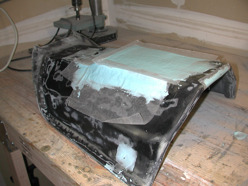
Next I use some aluminum to form a mold for the fiberglass layup. |
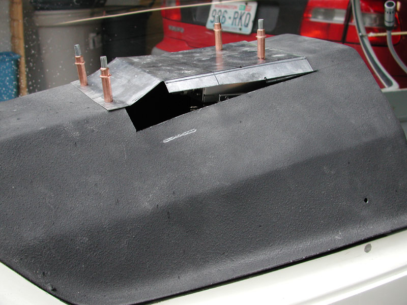 |
Below - I get the aluminum into the shape I want, cleco it into place and seal the mold with masking tape. |
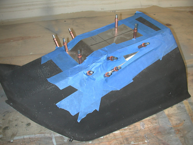 |
Below - the bottom, ready for fiberglass. |
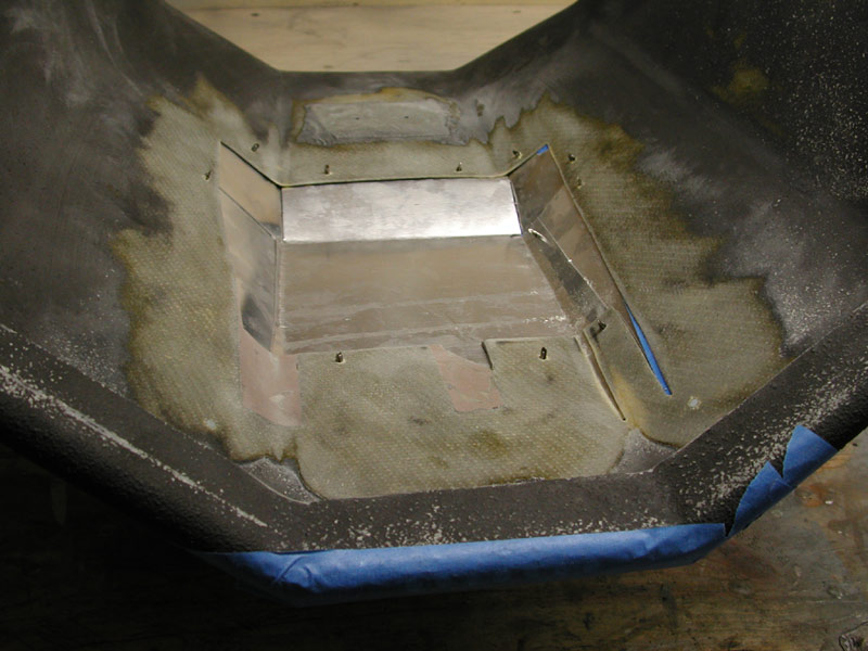 |
First I coat the aluminum with Partease parting wax, then I cut about 5 pieces of E glass to fit the mold. |
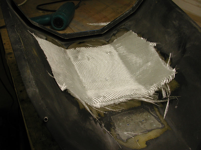 |
Below - the first few layers of fiberglass going in with MGS 285 epoxy resin. |
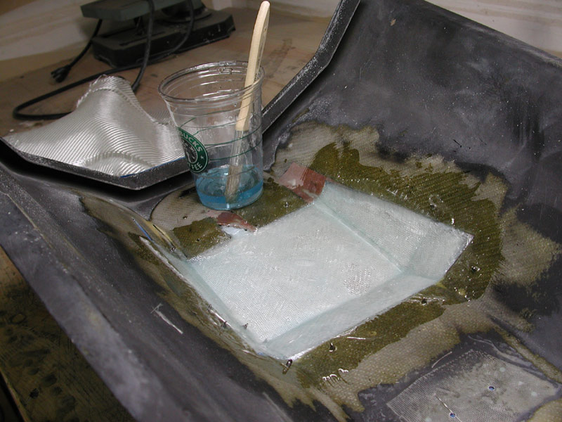 |
Below - all layers of fiberglass in place |
 |
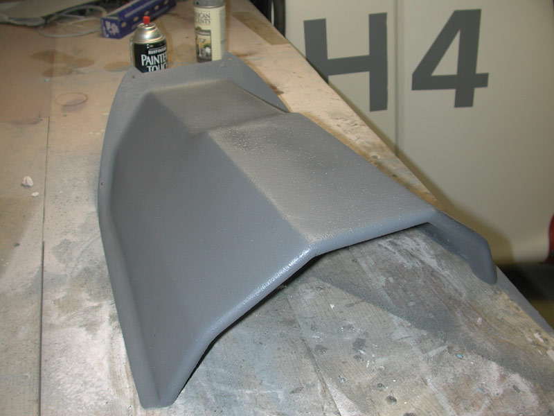
Below - after the fiberglass work is complete, I remove all of the instruments and stuff from the panel and paint it with a lighter shade of flat gray. I like this color much better. I painted over the fine texture finish and it shows through nicely. I plan to paint the glareshield the same color. I also painted the instrument mounting screws and the compass mount. Samson is lucky I didn't paint him, I was on a painting mission! |
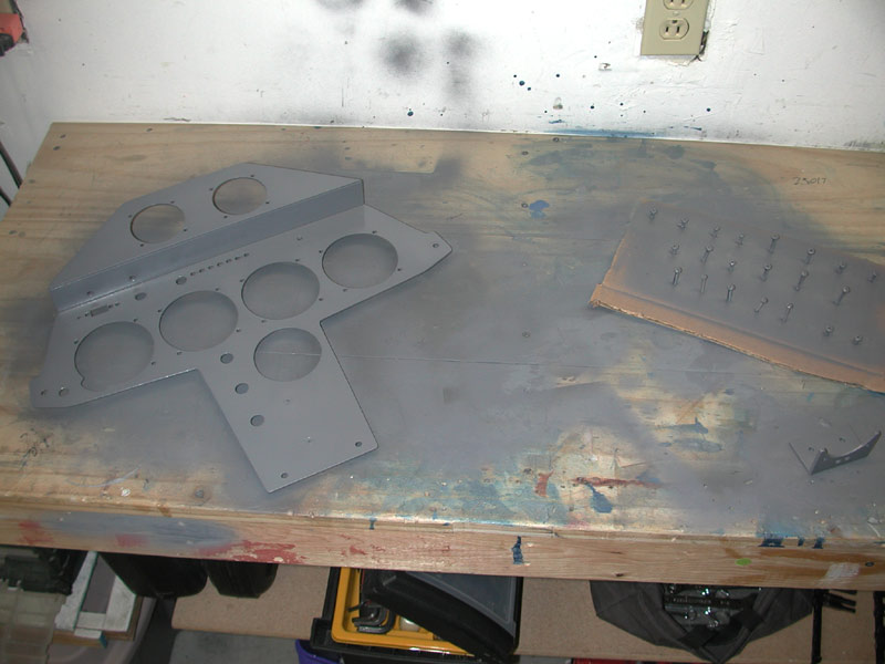 |
Below - 6 November 2005 - after the fiberglass sets up, I remove the aluminum mold pieces and masking tape, sand down the epoxy fiberglass composition to fair a bit and spread some Superfil over the top prior to sanding it smooth. Next some speckle paint followed by the new flat gray color that I've decided I like better than the old gray. |
 |
Below - while the Superfil hardens, I re-install the instruments into the newly painted panel. I like this grey color much better. I have the PC cable connected to the SN10b remote connection in order to upgrade the software to 2.31. |
 |
November 18, 2005 - I just spent the week in Oke City undergoing FAA training again. Below - After applying the speckle paint, I paint over the speckles with the same color gray primer that I used on the panel. This process eliminates any possibility of glare on the inside of the canopy. |
 |
Below - The primer is still wet in places. Tomorrow I'll finish wiring the radio and SN10; install the Volkslogger mount and some other stuff. I received new flap and gear handles from the UPS guy (McMaster-Carr) so I'll be fitting those as well. |
 |
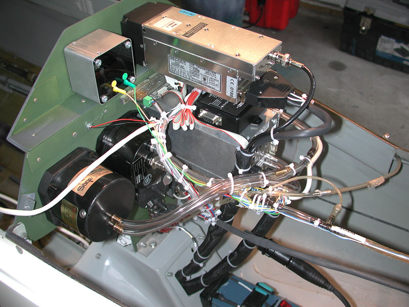
Below - November 20, 2005 - I finish wiring the new panel and radio. |
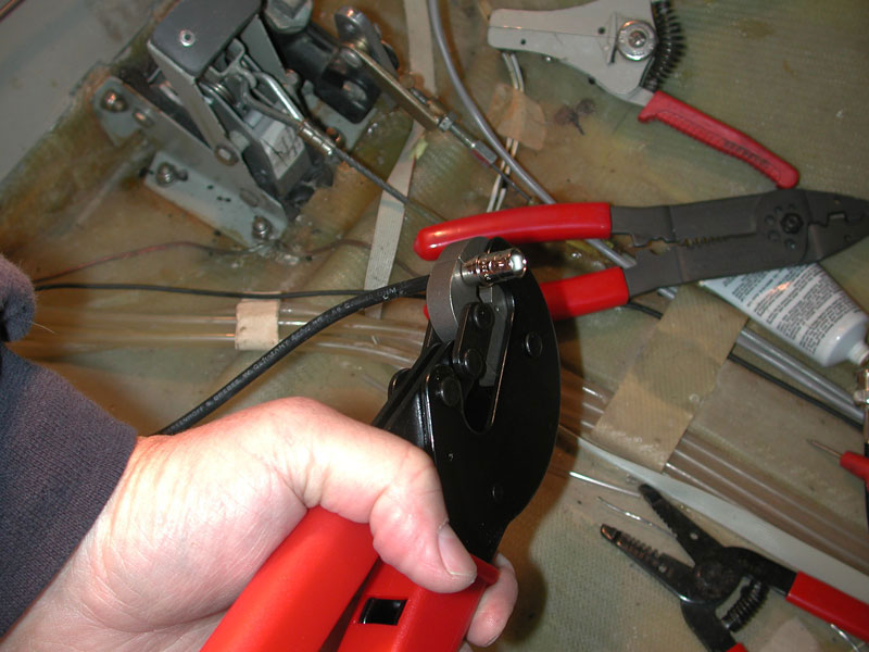 |
Above - the antenna coax is too short to reach the radio at the top of the panel, so I crimp on a male BNC connector to attach a new section of cable that runs from the new connection underneath the floor pan up to the back of the radio. |
 |
Above - tie-wrapping and sorting the wiring and tubing. |
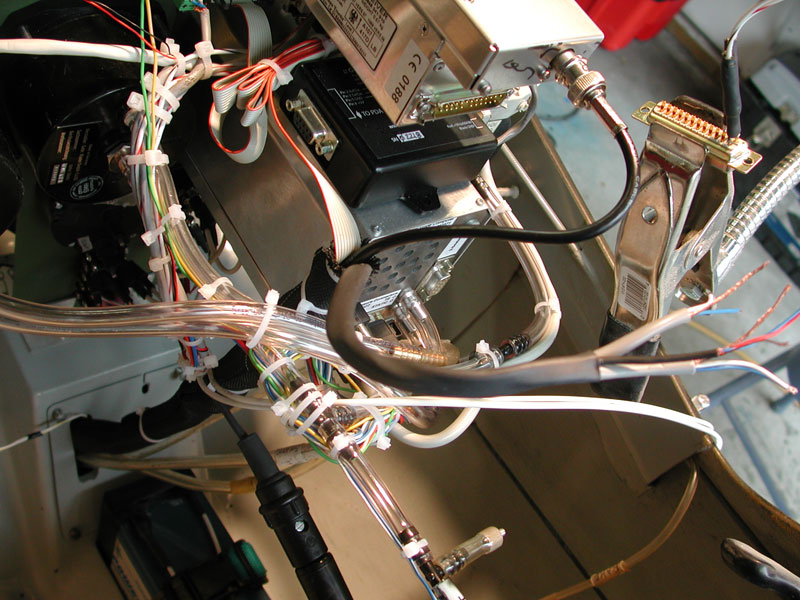 |
Above - getting set to terminate the radio wiring. Microphone, speaker, PTT wires all get stripped and tinned. Below I slip some small shrink tubing over the wires so I can push them up after soldering and protect the soldered connections. |
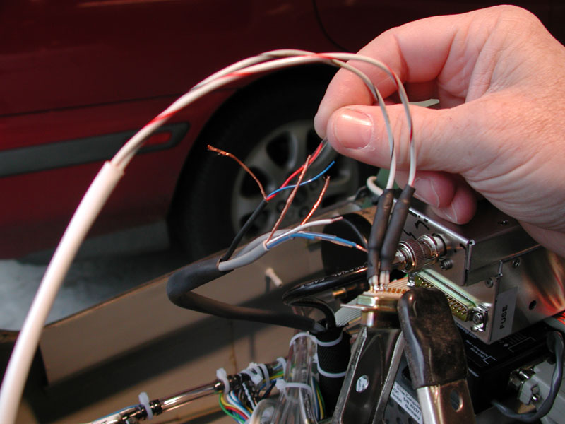 |
Below - soldering the wires to the DB25 for the Becker AR 4201. |
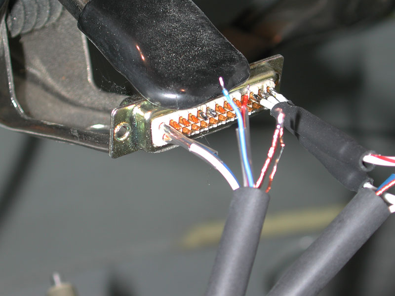 |
Below - the radio connector is finished and tested, works great. I finish tidying up the wires and tubing. Lots of tie-wraps and nylon fabric conduit. |
 |
Functional test - everything is working. |
 |
Below - it's cold (45°F) and the big dog says I either need to throw the ball or let him back inside. We're getting pretty soft with these mild Seattle winters, I've forgotten that it's below zero in some parts of the US this time of year. We don't miss it. |
 |
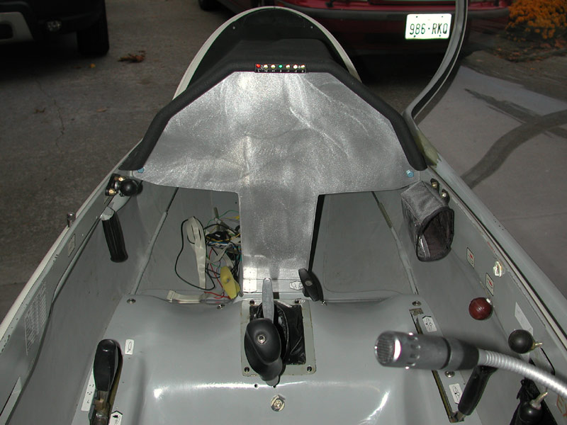
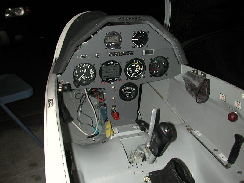
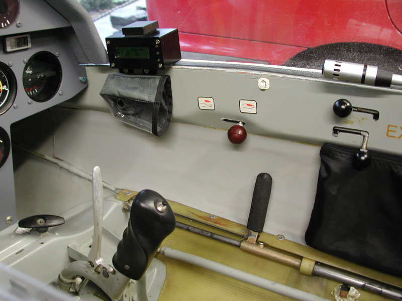
Below - 25 November 2005 - The Volkslogger is mounted on the right canopy frame rail. Here it will have a clear view of the sky and not obscure my view of the panel. The fabric pouch below the Volkslogger holds the EDS oxygen controller. The gear handle get a new foam grip to replace the aging and cracked ski pole grip. I need to reinstall the water ballast labels. |
 |
Below - The SN10b remote goes back in, the spoiler handle grip is removed for measuring so I can order a new one from Mcmaster.com. The gear warning indicator lights will be mounted in the center of the upper panel, between the radio and the RAZ meter. New flap handle from Mcmaster.com. |
|
The Volkslogger gets power from a dedicated wiring circuit through the guarded switch to the forward battery. The aft battery and forward battery are selected by the middle master switch, up for forward battery, center off, down for aft battery. The upper switch ties the two battery circuits together, up for bus tie on, down for bus tie off. I can run off either battery isolated or tie them together. This arrangement allows me to run them both (normal operation) and they if they both start to get low, I can switch to the aft battery for the main bus and open the bus tie. This will allow the forward battery to "rest" (with only the miniscule draw of the Volkslogger) and it will restore its voltage a bit, certainly keeping the Volkslogger powered for quite a while. |
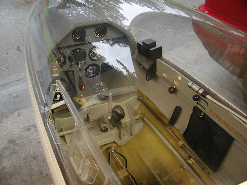 |
Below - The Cat5 cable comes out of the glareshield to plug into the Volkslogger. Hamilton vertical card compass goes back on top of the glareshield where it once was. |
 |
Old panel photos below. |
|
|
July 3, 2004 - new oxygen system mounted in cockpit, other minor changes made. |
|
Before |
 |
|
Below - New Goddard PS-5A power supply installed to run the iPaq and interface between the Volkslogger and SN10b. |
 |
March 14, 2003, new LED flap position indicator installed. |
 |
|
Below - 6 August 2002 - SN10B driven by the Volkslogger with meter mounted to the left replacing the clock. The SB-8 is gone and the PZL mechanical moves up to its old position. Winpilot running off the Volkslogger as well - 3 hour flight yesterday and everything works great. The SN10B is a very nice unit with lots of nice features. Very well thought out and easy to learn and use. |
 |
SN10B driven by the Volkslogger with meter mounted to the left replacing the clock. The SB-8 is gone and the PZL mechanical moves up to its old position. Winpilot running off the Volkslogger as well - 3 hour flight yesterday and everything works great. The SN10B is a very nice unit with lots of nice features. Very well thought out and easy to learn and use. |
 |
|
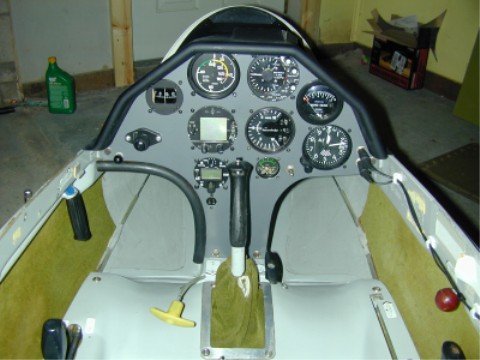
September 2001 - Below - While waiting for the gel-coat to set up on the vertical, I made a new instrument panel to accommodate the some new instruments. Top left is a new airspeed. Top right is a good, used SB-8 with speed-to-fly switch activated by zero or negative flap settings. Wing drag meter relocated to the upper right side and the GPS mounts under the compass. Filser ATR-57 left of the stick and battery meter to the right. Dual 7 ah batteries, new SPDT switch and circuit breaker round out the all-new electrical system. New flap handle (lower left) finishes the accommodations. |
 |
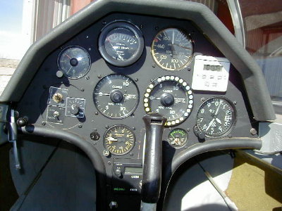
Here's the panel that came with the aircraft. From top left, there is a clock, wing drag meter, ASI, kitchen timer, moving to the lower left - the Ball speed-to-fly vario controls, Ball speed-to-fly vario, center right is another Ball Vario, altimeter, bottom is a g-meter and voltmeter. Charles kept the g-meter, timers, clock and radio and I re-did the panel as shown below. |
 |